Land Transport Rule
Heavy-vehicle Brakes 2006
Rule 32015
This is Schedule 5 of the Heavy-vehicle Brakes Rule.
Schedule 5 New Zealand Heavy-vehicle Brake Specification
1. Application
1.1 This specification is applicable to vehicles as required in Land Transport Rule: Heavy-vehicle Brakes 2006 (Rule 32015) (‘the Rule’).
1.2 A vehicle that is required to comply with the requirements in this specification must also comply with all other requirements as specified for the vehicle or its class in the Rule.
1.3 A vehicle that is not required to comply with this specification may also be manufactured or modified in accordance with the technical requirements in the specification.
2. Additional equipment requirements
2.1 Equipment or components fitted to a vehicle as part of its brake must be suitable for automotive application.
2.2 Equipment or components fitted to the brake of a vehicle must be appropriate, in respect of their nominal size, operational and performance characteristics and other relevant features, for the brake of the vehicle.
2.3 Brake components must be fitted and adjusted correctly, having regard to the manufacturer’s specification.
3. Additional system requirements for air brakes
3.1 An air brake of a powered vehicle must have two independent service-brake circuits.
3.2 If a vehicle is fitted with a spring-operated parking brake that is normally released by compressed air, the simultaneous application of the service brake and parking brake must not result in a compounded brake force on the axle or axles on which the parking brake acts. This may be referred to as an ‘anti-compounding’ requirement.
3.3 The air brake of a vehicle must be fitted with the additional equipment in 3, as applicable.
3.4 A pressure test connector as specified in Appendix D of the New Zealand Heavy Vehicle Brake Code, Second Edition (1997) must be fitted to a vehicle as follows:
- (a) to the inlet of at least one brake chamber, which is in the least favourable position, of the service brake on each axle set; and
- (b) to the upstream and downstream side of all valves that are fitted to modulate the pressure of the compressed air for the actuation of the service brake, including, but not limited to, ratio valves, load sensing valves and pressure limiting valves.
3.5 A drain valve must be fitted to the lowest point of each brake reservoir, specifically, the reservoirs of the service brake and park brake, and including the so-called ‘wet tank’.
3.6 An automatic drain valve must have a means of manual operation.
3.7 The compressed-air reservoir of auxiliary equipment connected to the air brake must also be fitted with a drain valve at the lowest point of the reservoir, if the manufacturer of the auxiliary equipment requires or recommends this.
3.8 A drain valve fitted to an air-brake reservoir or to the reservoir of auxiliary equipment must be capable of being operated by a person standing beside the vehicle, without the need for a pit or hoist.
3.9 If an air dryer is fitted to an air brake, the compressor capacity of the air brake must be sufficient to ensure the correct operation of the air dryer, having regard to the air dryer manufacturer’s recommendations.
4 Additional requirements for powered vehicles not used to tow heavy trailers
4.1 A two-axle powered vehicle that is not fitted with a towing connection to tow a heavy trailer must comply with the requirements in 4.1.1 and 4.1.2.
4.1.1 For a vehicle in 4.1, the following relationship must hold for the adhesion utilisation (fi) between a braking ratio (z) of 0.15 g and 0.8 g for both the front and rear axle:
![]()
4.1.2 For a vehicle in 4.1, when 0.15 ![]() z
z ![]() 0.3,
the adhesion utilisation:
0.3,
the adhesion utilisation:
- (a) of the rear axle must not exceed that of the front axle; and
- (b) of any axle must not be greater than z + 0.08; and
- (c) of any axle must not be less than z – 0.08.
4.2 A powered vehicle that has more than two axles and does not have a towing connection to tow a heavy trailer must comply with the requirements in 4.2.1 to 4.2.3.
4.2.1 For a vehicle in 4.2, the relationship in 4.1.1 must hold for all axles of the vehicle between a braking ratio of 0.15 g and 0.8 g.
4.2.2 For a vehicle in 4.2, and between 0.15 g and 0.3 g braking ratio (z), the adhesion utilisation for any of the axles must be within the limits specified in 4.1.2.
4.2.3 For a vehicle in 4.2, and between 0.15 g and 0.3 g braking ratio (z), the adhesion utilisation of at least one of the rear axles must not exceed the adhesion utilisation of the front axles or that of at least one of the front axles; and that rear axle must be:
- (a) the one that carries greater load if the rear axles are fitted with non-reactive suspension; or
- (b) for axles with reactive suspension that carry a similar load, the axle to which some load is transferred during braking due to the reactive suspension; or
- (c) for axles carrying a similar load and fitted with air suspension, the foremost axle in the axle set.
4.3 The requirements in 4 must be complied with at any load condition, and must be demonstrated by means of calculation carried out, at least, for the vehicle when unladen and when laden to its GVM. However, a vehicle that is fitted with ABS must only comply with this requirement, without relying on the operation of such a control device, when loaded to its GVM.
4.4 Compliance with the requirements in 4 may be shown by plotting the calculated adhesion utilisation curves for all front and rear axles in a diagram that also includes the permissible limits for the adhesion utilisation as specified in 4.1.1 and 4.1.2. (See also Figure 1, showing permissible limits for adhesion utilisation as a function of braking ratio.)
5. Additional requirements for air-braked powered vehicles that are used to tow heavy trailers other than semi-trailers
5.1 A vehicle in 5 must also comply with the requirements in 4, as applicable, according to the number of axles of the vehicle.
5.2 For a vehicle in 5, the following relationship must hold, when the control line pressure (pm) measured in kPa at the Duomatic or other type coupling connecting the air brake of the towing and towed vehicle is:
- (a) if 55 kPa
 pm 750
kPa, then
pm 750
kPa, then
z 0.044 + (pm – 55) x 0.756/695
and - (b) if 80 kPa pm 450
kPa, then
(pm– 80) x 0.35/370 z; and - (c) if 450 kPa pm 750
kPa, then
0.35 + (pm – 450) x 0.225/300 z
5.3 The requirements in 5.2 must be complied with at any load condition and demonstrated by means of calculation carried out, at least, when the vehicle is unladen and when laden to its GVM. However, a vehicle that is fitted with ABS must only comply with this requirement, without relying on the operation of such a control device, when loaded to its GVM.
5.4 Compliance with the requirements in 5 may be shown by plotting:
- (a) the calculated adhesion utilisation curves as specified in 4; and
- (b) the calculated braking ratio as the function of control-line pressure and the permissible limits specified in 5.2.
(See also Figure 2 showing permissible braking ratio limits as a function of control-line pressure.)
6. Additional requirements for air-braked full trailers
6.1 A full trailer must comply with the requirements both in 4, as applicable to the vehicle according to the number of axles fitted to the trailer, and with the requirements in 5.2.
6.2 The requirements in 6 must be complied with at any load condition, and demonstrated by means of calculation carried out, at least, when the vehicle is unladen and when laden to its GVM. However, a vehicle that is fitted with ABS must only comply with this requirement, without relying on the operation of such a control device, when loaded to its GVM.
6.3 Compliance with the requirements in 6 may be shown in the same way as in 5.4.
7. Additional requirements for air-braked powered vehicles used to tow semi-trailers
7.1 A vehicle in 7 must also comply with the requirements in 4 as applicable according to the number of axles of the vehicle, and also with the requirements in 5.2.
7.2 Despite 7.1, the braking ratio may exceed the limits specified in 5.2(a) if written permission has been obtained from the Director for the vehicle, but, in such a case, the following relationship must hold:
- when 55 kPa pm 650
kPa, then
z 0.044 + (pm – 55) x 0.756/595
(See also Figure 3, showing permissible braking ratio as a function of control-line pressure.)
7.3 The requirements in 7 must be complied with at any load condition and demonstrated by means of calculations, carried out, at least, when the vehicle is unladen and when loaded to its GVM. However, a vehicle that is fitted with ABS must only comply with this requirement, without relying on the operation of such a control device, when loaded to its GVM.
7.4 When compliance with the requirements in 7.1 is demonstrated by calculation, it must be taken into account that the vehicle carries a portion of the mass of the semi-trailer and that portion is increasing when the braking ratio is increasing.
7.5 For the purpose of calculations to demonstrate compliance with the requirements in 4 and 5 or 7.2, the factors in 7.5.1 to 7.5.4 must be taken into account.
7.5.1 The mass of the vehicle in an unladen condition, when a semi-trailer is not attached to the vehicle, is Mo.
7.5.2 The mass of the vehicle, when an unladen semi-trailer is attached, must be calculated as follows:
- Msu = Mo + 0.15 x Mso, where
- Mso is the permissible maximum load on the fifth wheel (or other type of coupling by which the semi-trailer is attached). It is the difference between the GVM and Mo.
7.5.3 The mass of the vehicle, when a fully laden semi-trailer is attached, must be calculated as follows:
- Ms = Mo + Mso x (1 + 0.45z)
7.5.4 When a calculation is carried out for a partially laden vehicle, the load on the fifth wheel may be calculated assuming a linear correlation between the static and dynamic load on the coupling by which the semi-trailer is connected. (For example, if the static load on the fifth wheel is half of the permitted maximum load, Mso, then at any braking ratio, z, the dynamic load is:
- Ms0.5 = Mo + 0.5 x Mso x (1 + 0.45z)
7.6 Compliance with the requirements in 7 may be shown by plotting the calculated braking ratio as a function of control-line pressure and the permissible limits specified in 5.2 or 7.2 as applicable. (See also Figure 2 and Figure 3.)
8. Additional requirements for air-braked semi-trailers that are used to tow another semi-trailer (first semi-trailer of a B-train)
8.1 A vehicle in 8 must comply with the requirements in 4, for the adhesion utilisation and the requirements in 5.2, for the braking ratio.
8.2 The requirements in 8.1 must be complied with at any load condition and demonstrated by means of calculation. However, a vehicle that is fitted with ABS, must only comply with this requirement, without relying on the operation of such a control device, when loaded to its GVM.
8.3 The calculation in 8.2 must be carried out, at least, for the unladen condition and when the vehicle is loaded to the GVM, however, for the purpose of calculations the mass that is carried on the axle set of the semi-trailer must be taken as follows:
- (a) for an unladen vehicle to which no other semi-trailer can be attached, the load on the axle set of the unladen semi-trailer is MR0;
- (b) for an unladen semi-trailer to which another unladen semi-trailer is attached, the unladen mass of the semi-trailer is MRU;
- (c) in a fully-laden condition the maximum permitted load of the axle set is MR, as in the Certificate of Loading of the semi-trailer.
8.4 Compliance with the requirements in 8 may be shown by plotting:
- (a) the calculated adhesion utilisation curves as a function of braking ratio;
- (b) the calculated braking ratio as a function of control-line pressure and the permissible limits specified in 5.2.
(See also Figure 2 and Figure 3.)
9. Additional requirements for air-braked semi-trailers that are not used to tow another semi-trailer
9.1 A vehicle in 9 must comply with the requirements in 4 for the adhesion utilisation and the requirements in 5 for the braking ratio.
9.2 The requirements in 9.1 must be complied with at any load condition, and they must be demonstrated by means of calculation, except that a vehicle that is fitted with ABS, must only comply with this requirement without relying on the operation of such a control device, when loaded to its GVM.
9.3 The calculation in 9.2 must be carried out, at least, when the vehicle is unladen and when laden to its GVM. However, for the purpose of calculating the braking ratio, the mass that is carried on the axle set of the semi-trailer must be taken as follows:
- (a) for an unladen vehicle, the mass that is carried on the axle set is MR0;
- (b) for a fully laden vehicle, due to the dynamic load transfer from the semi-trailer to the towing vehicle (MRL):
MRL = M – Mkp x (1 + 0.45z), where
M is the GVM, and Mkp is the static load carried by the kingpin when the vehicle is loaded to its GVM.
9.4 Compliance with the requirements in 9 may be shown by plotting:
- (a) the calculated adhesion utilisation curves as a function of the braking ratio; and
- (b) the calculated braking ratio as a function of control-line pressure and the permissible limits specified in 5.2.
(See also Figure 2 and Figure 3.)
10. Requirements for the calculations in this specification
10.1 A calculation to demonstrate compliance with the requirements in this specification must be carried out by using computer software that has been approved by the Director.
10.2 A calculation may also be carried out manually, ie, by ‘long-hand’ calculation.
10.3 For the purpose of calculating the adhesion utilisation of the axles of a two-axle powered vehicle or full trailer at any load condition and at any braking ratio, the following formulae must be used:

 where
where- f1 and f2 are the adhesion utilisation values for the front and rear axles;
- T1 and T2 are the brake forces on the front and rear axles;
- N1 and N2 are the dynamic vertical reaction forces at the front and rear axles on the road (ie, the dynamic load carried on the axle);
- M1 and M2 are the mass carried on the front and rear axle in static condition;
- z is the braking ratio;
- h is the height of the combined centre of gravity of the vehicle and the load, measured from the ground;
- M is the mass of the vehicle and the load carried, ie, the sum of M1 and M2;
- E is the wheelbase.
10.4 The height of the centre of gravity for a powered vehicle not towing a semi-trailer, and also for a full trailer must be calculated as follows:
where:
-
h0 is the height of the centre of gravity of the unladen vehicle, measured from the ground;
Mo is the mass of the unladen vehicle;
hl is the height of the centre of gravity of the load, measured from the ground;
Ml is the mass of the load;
M is the combined mass of the vehicle and the load.
10.5 The centre of gravity of a laden, powered vehicle towing a semi-trailer must be calculated in a similar way, however, the height of the centre of gravity for the load is the height of the fifth wheel or other coupling around which the semi-trailer pivots, and the mass of the load must be calculated as specified in 7.5.
10.6 The braking ratio, z must be calculated as follows, unless 10.7 applies:
where:
- Ti is the brake force on axle number i;
- Md is the dynamic mass of the vehicle, which is the mass of the unladen vehicle together with the mass of the load carried and the load, if any, that is transferred onto the vehicle from another vehicle or from the vehicle to another vehicle as a result of braking;
- g is the acceleration due to gravity.
10.7 The braking ratio for a semi-trailer must be calculated in a similar way to that in 10.6, but instead of the dynamic mass of the vehicle being used, the dynamic load carried on the axle set of the semi-trailer as specified in 9, must be used.
11. Information required to ensure compliance with this specification
11.1 The brake performance of an axle must be provided by the axle manufacturer or brake manufacturer, and must be in the form of output versus input (for example, for hydraulic brakes, brake torque v. hydraulic pressure; for air-operated drum brakes, brake torque v. S-cam torque, or for air-operated disc brakes, brake torque v. air pressure (in the brake chamber).
11.2 The data in 11.1 must be based on tests that were carried out in accordance with one of the standards in 2.5(2) of the Rule, when the brake was fitted to a vehicle with a GVM similar to the vehicle to which the axle is being fitted, and in a position (front or rear) to which the axle is being fitted.
11.3 The performance data in 11.1 can only be acceptable as valid for a brake calculation and certification if the brake drum or disc and friction material are identical with the ones that were tested, and the nominal size of the S-cam, brake chamber or cylinder and any other component that may affect the performance of the brake are the same as specified by the axle manufacturer or brake manufacturer.
11.4 If the performance of the brake in 11.1 is not available from the vehicle manufacturer or brake manufacturer, it must be established and verified by means of stopping tests. Those verification tests must be carried out with a vehicle sufficiently loaded to prevent premature wheel lock-up during testing, using only the brakes on the axle, the brakes of which are being tested. The tests must be carried out from an initial speed of approximately 50 km/h on a level surface.
11.5 During the test in 11.4 the average deceleration of the vehicle and the air or hydraulic pressure, in the brake chamber or cylinder as applicable, must be measured. During the tests, the pressure in the brake chamber or hydraulic cylinder must be steady and be at least 60% of the maximum pressure that occurs at full brake application.
11.6 The performance of the brake, when applied as in 11.5, must be calculated from the average deceleration and the pressure, specified in 11.5, the mass of the vehicle during testing and the rolling radius of the tyre measured at the time of the test.
11.7 The performance of the brake at low-intensity brake application must be established by measuring the pressure in the brake chamber or cylinder when a brake torque or force is generated that can be detected when the axle of the vehicle is lifted and the brake is gradually applied.
11.8 For the purpose of brake calculations, it may be assumed that a linear correlation exists between the brake torque produced by the brake and the pressure in the brake chamber or brake cylinder.
11.9 The brake performance as established by means of tests in 11 can only be considered valid for subsequent brake calculations and certifications if the conditions in 11.3 are met.
12. Information to be provided to the operator
12.1 The certifier who certifies a vehicle for compliance with this specification, or a manufacturer who manufactures a vehicle in compliance with this specification, must provide the operator with the following information:
- (a) the make, type and grade of the friction materials fitted to the brake;
- (b) the make, model and type of all valves that are fitted to the brake system;
- (c) the settings of adjustable valves (eg, ratio valves, pressure limiting valves, etc.);
- (d) the setting and adjustment of the valves that ‘self-adjust’ during operation (eg, load sensing valves);
- (e) the size, including the stroke, of the brake chambers or cylinders;
- (f) the make, model and type of any other component of the brake that may affect the correct operation of the brake system if replaced with a different make, model or type (eg, booster cylinders).

Figure 1 Adhesion utilisation as a function of braking ratio

Figure 2 Braking ratio as a function of control-line pressure
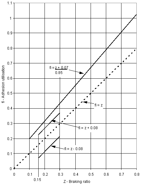
Figure 3 Braking ratio as a function of control-line pressure
(Special case, requires approval from the Director)
Land Transport Rule - Heavy-vehicle Brakes - Rule 32015
Land Transport Safety Authority of New Zealand, Te Mana Marutau Waka Whenua o Aotearoa